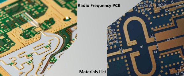
RF PCB Materials: Comparing PTFE and FR4 for High-Frequency Applications

Selecting RF PCB Materials:
Microwave electronics and PCBs function at signal frequencies from low MHz to high GHz (mmWave range). These advanced products are crafted from a mix of synthetic and natural materials to maintain reliable operation and signal integrity at these high frequencies. Material selection is crucial for designing high-performance microwave PCBs.
RF PCB materials possess specific properties essential for their use in printed circuits, interconnect boards, or standalone assemblies, including dielectric constant, thermal expansion coefficient (CTE), and loss tangent. Additionally, the copper material in an RF PCB stackup is vital due to its surface roughness, which influences the skin effect experienced by signals during propagation.
RF PCB Layer Stacks:
The first thing to decide while designing a PCB stackup for a microwave electronics assembly or RF PCB is which materials are required. In the past, PCB designers had limited material options. Today, a wide range of low-loss dielectric materials for microwave PCBs are available from different manufacturers. The primary materials to select and balance in an RF PCB stackup design include:
--- Laminate and bondply layers
--- Copper foil
--- Surface plating
--- Any surface coatings, such as solder mask and conformal coatings
Most of today’s RF PCB materials are polytetrafluoroethylene (PTFE)-based materials. PTFE is an engineered thermoplastic fluoropolymer with low dielectric losses at microwave frequencies. The dielectric constant can range from very small values to very large values, which allows the required size of RF printed circuits to be adjusted simply by selecting an alternative material. Three of the most popular RF materials manufacturers include Rogers, Taconic, and Arlon.
What are the key differences between PTFE and FR4 PCB materials?
Dielectric Properties:
- PTFE: Lower dielectric constant and loss tangent, making it ideal for high-frequency applications.
FR4: Higher dielectric constant and loss tangent, suitable for standard applications but less effective at high frequencies.
Temperature Resistance:
- PTFE: Excellent thermal stability, can withstand higher temperatures without degrading.
FR4: Moderate temperature resistance, suitable for standard operating conditions.
Cost:
- PTFE: Generally more expensive due to its specialized properties.
FR4: More cost-effective and widely used in many applications.
Mechanical Properties:
- PTFE: Superior chemical resistance and lower friction properties.
FR4: Good mechanical strength but less chemical resistance compared to PTFE.
Applications:
- PTFE: Primarily used in high-frequency, microwave, and RF applications.
FR4: Commonly used in general-purpose electronics, including consumer products.
PTFE and FR4 are two of the most used PCB design materials, and it’s important to understand the difference between them. FR4 is a standard defined by National Electrical Manufacturers Association (NEMA), referring to glass-reinforced epoxy laminate material. The "FR" in FR4 stands for "flame retardant." While FR4 materials are common and they cost less, PTFE is a better choice for RF/microwave PCBs operating well above WiFi frequencies.
RF PCB Materials List:
The chart below shows the basic properties of various RF PCB materials sorted by dielectric constant at 10 GHz. We’ve compiled a complete list of materials from major microwave PCB laminate manufactures like Rogers and Arlon. We hope this list can help you compare your material options and make the best decision for your new design.
Please download the Materials List from here.
 The Evolution of PCB Technolog
 Top 6 PCB Industry Trends Shap
 Sustainable Materials and Manu
 The Impact of DeepSeek, NVIDIA
